

UCT2100(50) Chain Cutting & Press-Fit Tool Instructions
The UCT2100(50) can cut 420, 428, 520, 525, 530, and 532 Sealed and Non-Sealed chains.Use protective gear such as safety glasses or face guard and anti-slip gloves when using the RK Chain Tool.
DO NOT CUT MASTER LINK !
DO NOT USE TOOL TO CUT 630 & 632 TYPE CHAIN
DO NOT USE IMPACT WRENCH OR DRIVER
DO NOT USE TOOL TO CUT 630 & 632 TYPE CHAIN
DO NOT USE IMPACT WRENCH OR DRIVER
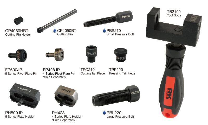
| Part # | Purpose | Chains |
|---|---|---|
| PH500JP | Press Fit | 520, 525, 530, 532 Sealed Chain |
| PH500JP | Rivet | 520, 525, 530, 532 Sealed & Non-Sealed Chain |
| PH428* | Press Fit | 428 Sealed Chain |
| PH428* | Rivet | 428 Sealed & Non-Sealed Chain |
 LUBRICATE WITH GREASE
TO BREAK A CHAIN
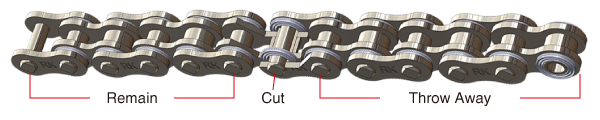
Lock the chain with the chain tool and push out pin from the chain.Note: If you are cutting a new chain to length, be sure to remove the chain pin that will leave you with inner side plates as the end of the chain.
A connecting link can only be installed onto inner side plates.
(Figure A)
A: When chain cutting, cut only outer plates.
1.
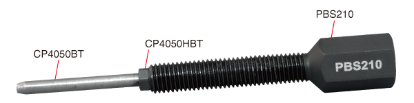
By default the cutting pin assembly (Figure 1A) will be assembled in the kit, but if disassembled to replace parts, follow these directions.
Slide the cutting pin holder CP4050HBT onto the cutting pin CP4050BT. Thread the cutting pin holder CP4050HBT into the small pressure bolt PBS210 (Figure 1A).
1A: Cutting Pin Assembly – Complete
Slide the cutting pin holder CP4050HBT onto the cutting pin CP4050BT. Thread the cutting pin holder CP4050HBT into the small pressure bolt PBS210 (Figure 1A).
1A: Cutting Pin Assembly – Complete
2.
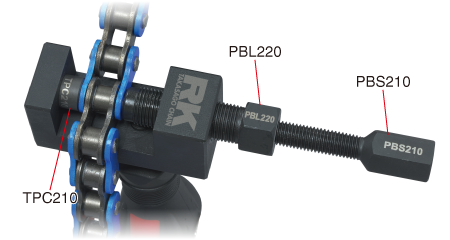
Thread the large pressure bolt PBL220 into the tool body TB2100 (Figure 1B).
3.
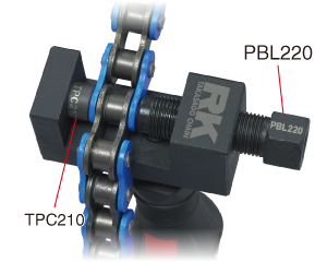
Insert the chain cutting tail piece TPC210 into the opposite side of the tool body TB2100 (Figure 1B).
4.
Position the chain to be cut between the hole in the end of the large pressure bolt PBL220 and the hole in the tail piece TPC210 (Figure 1B).
1B
1B
5.
Using a 17mm wrench, tighten the large pressure bolt PBL220 so that the chain is held fi rmly in place and centered on the pin. If the large Pressure bolt PBL220 is not seated directly on the chain the cutting pin CP4050BT can break and damage your chain.
6.
Thread the Cutting Pin Assembly (Figure 1A) into the large pressure bolt PBL220 (Figure 1C).
1C
Cutting Pin Assembly (Figure 1A) Installed in Large Pressure Bolt PBL220
1C
Cutting Pin Assembly (Figure 1A) Installed in Large Pressure Bolt PBL220
7.
Using a 14mm wrench, turn the small pressure bolt PBS210 until the chain pin is pushed completely through the side plates.
8.
CAUTION: The first few turns will be very hard as the quad stake riveted edges on the chain pin are pushed through the side plate. If it seems exceptionally hard, check the alignment of the chain pin with the hole in the end of the large pressure bolt PBL220 and cutting tail piece TPC210.
INSTALLATION/PRESS-FITTING OF SIDEPLATE FOR CLIP AND RIVET
1.
Review the drawings for reference. Route chain over and around counter shaft sprocket (Figure 2A).
2A

2A
2.
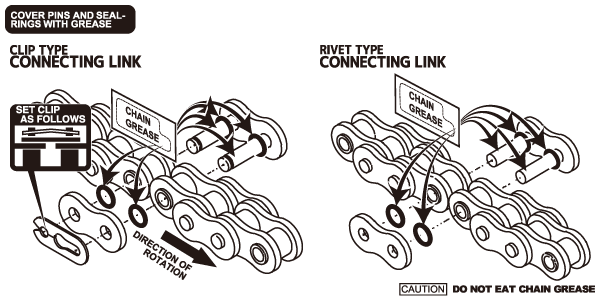
New RK Chain connecting link bags contain a small bag of grease. Follow the instructions on the connecting link bag. Make sure you apply the grease to all components of the connecting links including pins and if applicable O-rings (Figures 2B). If the chain is sealed (contains Orings) put 1 greased O-ring over each connecting link pin. Slide the pins through the two ends of the chain from the back to connect the chain near the bottom of the rear sprocket (Figures 2B).
2B
2B
3.
If applicable, put the other two greased O-rings over each pin on the other side of the chain (Figures 2B).
4.
Plate Holder Selection
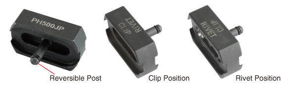
PH500JP (Figure 2C)- To Press-fi t Clip & Rivet sideplates for 520/525/530/532 O-ring.
*PH428 – To Press-fi t Clip & Rivet sideplates for 428 Chains
*Sold Separately
2C
PH500JP (Figure 2C)- To Press-fi t Clip & Rivet sideplates for 520/525/530/532 O-ring.
*PH428 – To Press-fi t Clip & Rivet sideplates for 428 Chains
*Sold Separately
2C
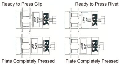
5.
Unscrew the post in Plate Holder PH500JP or PH428 to switch between clip and rivet position (Figure 2C, 2D and 2E) Insert the correct plate holder PH500JP or PH428 (see Plate Holder Selection above) into the large pressure bolt hole PBL220 and position the connecting link side plate in the plate holder PH500JP or PH428 (Figure 2D).
2D

2E
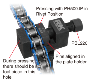
6.
Align the pins of the chain with the indent in the PH500JP or PH428 plate holder (Figure 2D & 2E).
7.
Turn the large pressure bolt PBL220 by hand making sure to keep the pins and side plate holes aligned until snug.
8.
Use a 17mm wrench to tighten the large pressure bolt PBL220. The side plate should press-fi t fi rmly but without diffi culty.
9.
Tighten bolt to correct depth allowed by plate holder channel. Do not over-torque (Figure 2F). Loosen large pressure bolt PBL220 and remove tool from the chain. Remove Plate Holder PH500JP or PH428 from large pressure bolt PBL220.
2F
2F
10.
The chain’s sideplates are now press fi tted to the chain. Proceed to installing the Clip or Rivet in the next section.
Important: RK recommends using rivet type connecting links whenever possible for the most secure connection.
INSTALLING THE CLIP
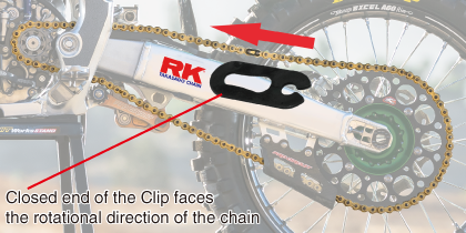
1.
Using thin-nose pliers, snap clip into pin grooves with closed end of clip facing rotational direction of chain (Figure 3A).
3A
3A
2.
WARNING: Make sure the clip is properly tension-seated in the groove of the pins. If the clip is loose, adjust the side plate up the pins with pliers until it is snug against the clip. NEVER REUSE A CONNECTING LINK.
NOTE: After installing the clip or rivet, inspect the connected links to make sure there are no links that are bound or stiff (Figure 3AA).
3AA
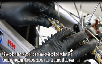
NOTE: After installing the clip or rivet, inspect the connected links to make sure there are no links that are bound or stiff (Figure 3AA).
3AA
INSTALLING THE RIVET
Lock the chain together using a rivet link. Chain tool fl ares the two open holes on the sideplate pins to secure plate to the connecting link.First, follow procedures 1-10 in the Installation/Press-fitting of Sideplate for Clip and Rivet.
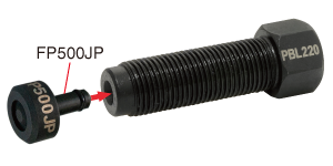
1.
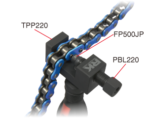
Thread the large pressure bolt PBL220 into the tool body TB2100. Once threaded partially into the tool, insert fl are pin FP500JP into the large pressure bolt PBL220 (Figure 3B).
Insert tail piece TPP220 into hole in tool wall opposite the large pressure bolt PBL220 (Figure 3C)
Insert tail piece TPP220 into hole in tool wall opposite the large pressure bolt PBL220 (Figure 3C)
3B
3C
2.
Align the fl are pin FP500JP with the hole in the end of the connecting link pin. Make sure the other end of the connecting link pin is seated in the tail piece TPP220 (Figure 3C). Tighten the large pressure bolt link pin hole (Figure 3C).
3.
Use a 17mm wrench to tighten the large pressure bolt PBL220 until the pin hole is fl ared out suffi ciently to keep the side plate from coming off. The fl are pin FP500JP will correctly fl are the rivet to the correct depth/width (Figure 3D). Repeat this procedure for
the second pin.
* Flare dimensions according to RK Chain
3D
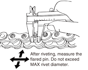
| Rivet Tool Diameters | ||
|---|---|---|
| Rivet Flare Pin Type | 4 Series FP428JP | 5 Series FP500JP |
| Plate Holder Type | 4 Series PH428 | 5 Series PH500JP |
| MAX Rivet Diameter | 4.65mm +0.1-0 | 5.55mm +0.1-0 |
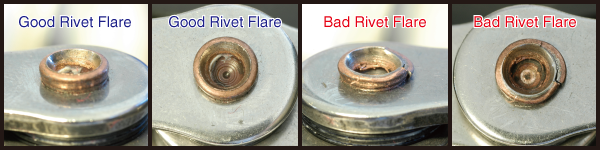
WARNING: Tighten the large pressure bolt PBL220 only until fi rm resistance is felt, then loosen the large pressure bolt PBL220 and inspect the connecting link pin for complete, even fl aring. Do not over-tighten the bolt – you may bend or damage the link pins or bind the link entirely. A pronounced, even fl are will securely connect the chain links together.
Check to make sure there is no crack on the flare.
You can download PDF from here.

